
Infrastructure and Facilities
This project will take advantage of the significant experimental and testing infrastructure and experience available to the members of the NASCE Consortium. We plan to design data collection and evaluation experiments as discussed in the proposal by leveraging the hardware and computing resources of the networking experimental platform that has been established by the PI team at the Institute for the Wireless Internet of Things, Northeastern University, the University of Oklahoma, Florida International University, UC Berkeley’s Space Science Laboratory, UCSB, NCSU, Texas A&M University, UT Austin. The platform consists of components that span air, underwater and ground programmable wireless and computing infrastructure that can be used for both sensing and communications. It is a truly distributed platform, spanning several University campuses in the U.S., with facilities including multiple software-defined testbeds, radars, antenna fabrication facilities, and a massive compute infrastructure. In addition to the technical facilities and equipment, NASCE benefits from collaborative/managerial facilities and equipment, as well as institutional support resources.

Large-Scale Radio Facilities
Colosseum. Colosseum is a massive RF and computational facility that emulates wireless signals traversing space and reflecting off multiple objects and obstacles as they travel from transmitters to receivers. As such, it can create virtual worlds, as if the radios are operating in an open field, downtown area, shopping mall, or a desert, by generating more than 52 terabytes of data per second, far exceeding the amount of information contained in the entire print collection of the Library of Congress.
At a high-level, Colosseum comprises two tightly interacting blocks: (i) a set of 128 software-defined radio resources, called standard radio nodes (SRNs), each containing two RF frontends and abundant computational capabilities, and (ii) a massive channel emulator (MCHEM), which is also equipped with 128 receiving radio interfaces (RRIs). In a nutshell, Colosseum is based on the following main operations. The SRNs are tasked with generating up to 128×2 customized RF full-stack waveforms, which are then transmitted over-the-wire and received by an additional set of 128 RRIs. The MCHEM provides repeatable, real-time, large-scale channel emulation by concurrently processing up to 256×256 (i.e., full-mesh) interactions between the SRN and the RRIs, thus enabling the emulation of wireless networks composed by up to 256 wireless devices operating concurrently.


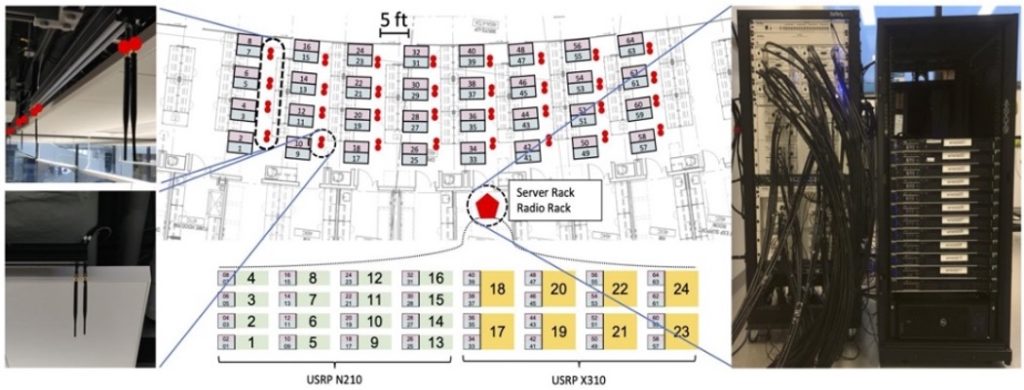
Arena. Arena consists of a large-sized 64-antenna ceiling testbed with 24 NI USRPs (16 N210 and 8 X310) equipped with a CBX daughterboard. The testbed covers an indoor office area of 2240 square ft within the fourth floor of Interdisciplinary Science and Engineering Complex (ISEC) at Northeastern. This environment is an indoor multi-disciplinary open-space research laboratory (as shown in the figure on the left), characterized by low-speed mobile patterns and heterogeneous obstacles, resulting in a challenging scenario with high multi-path and dynamic reflections effects.
An overhead architecture of 64 0-6GHz antennas following an 8×8 grid is put in place in an indoor lab/office environment, without RF damping cones on the walls. Thus, there exist rich multipath, external interference, human mobility, uncontrolled electrical hum, among other wireless artifacts at any time in this shared space.
IPG. Innovation Proving Ground (IPG) is a $50 Million facility under construction at the TAMU RELLIS campus, a former US Air Force base located about 10 miles from TAMU main campus. $15 Million is going into the instantiation of a state-of-the-art 5G and beyond testbed, spread out over 6 square kilometers with indoor, outdoor and mobile communication experiment facilities. The network will consist of both a production-grade test network and a fully programmable research network, and includes access to a data center. Mast mounted antennas and power amplifiers will enable realistic over-the-air experiments to support a wide range of application scenarios.

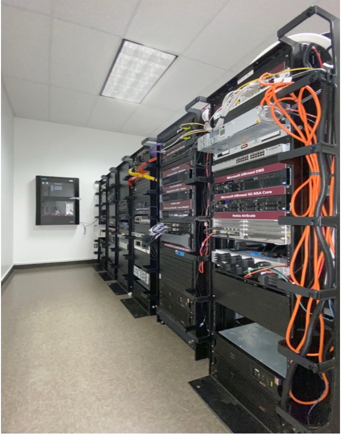
AWARE. Advanced Wireless Research Application Environment (AWARE) is a 4G/5G Testbed (figures on the left) designed to support advanced applications that require 4G and 5G network access. It has evolved since 2004 and currently represents an approximate $8 million investment in hardware, software, devices, applications and services most of which has been donated by industry.
AWARE includes a 5G Non-Stand-Alone Microsoft (Affirmed Networks) core, including Enterprise Management Server (EMS) and an Open Network Architecture (ONA) core, Radio Access Network (RAN) from Nokia, AirSpan, Star Solutions open source and Parallel Wireless. Spectrum currently used includes Bands 14,41 and 48). We also have over 100 UEs from Sonim, Zebra, Motorola, open source, Sierra Wireless and Cradle Point. A 5G Stand Alone upgrade is anticipated for December of 2021. Connectivity between eNodeBs and the core is provided by Cisco switches, a Juniper router and GPS clocking provided by a Spectracom Netclock through the Precision Timing Protocol (PTP). Additional network support systems include a Fortinet IPSec router, currently supporting connections to Columbia University, the University of Florida and Texas A&M University at Commerce. AWARE also includes an private InfoBlox DNS appliance and Active Directory server, Palo Alto perimeter security appliance and several Dell R740 servers with associated storage arrays running under VMware hypervisors.
The applications that can be used to run on top of the wireless network include a full NG 9-1-1 Emergency Services IP network (ESInet), PSAP workstations, legacy gateways and Border Control Functions (BCFs). Video includes a Genotech video server, Skyline Video Streaming service and several cameras. Voice services include a carrier grade softswitch from Broadsoft (now Cisco), complete set of Avaya Aura servers, a Cisco Call Manager enterprise solution and Session Border Controllers from Ribbon, InDigital, Cisco, Avaya and Acme Packet (Oracle). Situational awareness applications include Blueforce and Intrepid. AWARE also has a set of LMR to SIP gateways and access to the regional P25 network for research purposes. The ITEC includes a 600 square foot server room with DC power plant, UPS backup and a stand-alone Liebert air handling system. It is only filled to approximately 50% capacity at this time. The ITEC has two CBRS Certified Professional Installers, contracts with two Spectrum Access Server providers. TAMU holds a CBRS PAL and has shared access to 4 EBS licenses (A, B, C and D 1-4). TAMU also has two Home Network Identifiers (HNIs).
Extreme Spectrum Programmability Facilities
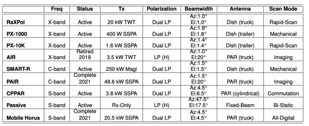

ARRC radar facilities at OU. The strategic focus at OU on the interdisciplinary field of weather radar has provided exceptional resources for developing radar systems and supporting field experiments, which make the proposed effort feasible. Under OU’s Strategic Radar Initiative, existing and newly hired faculty members were united to form the interdisciplinary Advanced Radar Research Center (ARRC) with the mission of solving challenging radar research problems, preparing students to become the next generation of scientists and engineers, and serving to empower economic growth and development in the field of weather radar. Currently, ARRC has 20 faculty members, 18 radar engineers/technicians, 1 professional project manager, and more than 100 undergraduate and graduate students, postdocs, and visiting scholars from meteorology, hydrology, and engineering. The ARRC operates and/or has access to a unique and extensive set of instruments to investigate existing areas of study, and to explore new and important research fields. As shown in the table on the left, the ARRC operates and/or has access a diverse set of radars of complementary wavelengths, scanning options, and polarimetric capabilities.
An important point is that the ARRC has a long history of effectively maintaining and operating radars for a diverse set of user applications. The proposed testbed will make extensive use of these facilities.
The Mobile Horus is nearing completion in 2021 and represents the most advanced weather radar in the ARRC’s arsenal of radars. The all-digital phased array system shown in the photograph is a 1024-element engineering demonstrator that has been developed with funding from NOAA and the Navy. Its goal is to mitigate risks associated with a modern/future all-digital phased array architecture for multi-mission weather and surveillance radar. Because this demonstrator is limited in size both by the requirement for mobility and by limited funding, it has a 4.5 beamwidth that is suitable for demonstrations of basic functionality and overall scalability, using waveforms, digital beamforming, control/calibration schemes, and power levels that are consistent by design with full-scale systems and can serve as an ideal proxy for future operational weather radars.
The Radar Innovations Laboratory (RIL) building for the ARRC, which opened during the fall of 2014, is a 35,000 square foot state-of-the-art facility for Radar research. The RIL has two precision anechoic chambers with dimensions of 27x38x27 ft3 and 13x26x13 ft3, both with isolation of at least 100 dB up to 18 GHz of operation. In addition to the anechoic chambers, the RIL has a dedicated machine shop, high-bay garage, experimental observation roof deck, and a unique “Ideas Room” with state-of-the-art interactive technologies, which is designed to enhance collaboration among researchers and students across locations to move ideas from conception through early research and development to full prototyping and product creation. The microwave lab provides more than 4,000 square feet of lab space and state-of-art test equipment covering DC to 110 GHz.
Ultra Agile Spectrum Server. The team has access to an Ultra-agile Spectrum Server, which enables real-time data collection and analysis of RF signals through a multi-function wideband sub-array and an adaptive RF front-end. The server will allow dynamic spectrum access experiments in the spectrum range between 2 GHz and 18 GHz. Specifically, the incoming/outgoing data is processed at 1 GHz through a Xilinx RFSoC.
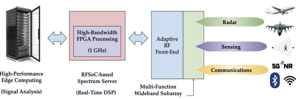
This way, the spectrum server combines wideband processing with many multiple degrees of freedom to protect and exploit the spectrum, with applications to communications, radar, and sensing. The system uses the VITA 49.2 standard to provide high speed data and low latency control interfaces that are agnostic to RF functions and supports distributed spectrum operations through the usage of NTP. The system will provide multiple degrees of freedom to access spectrum, including the precise specification of time, duration, power, frequency, instantaneous bandwidth, beamforming, and other signal characteristics. The RFSoC is connected to (i) a 56TB NAS that can store 3 hours of spectrum observation for 1 GHz of bandwidth; and to (ii) a high-performance GPU-based edge computing system, which can perform real-time signal analysis and baseband processing.

Millimeter Waves and Terahertz. The team is the developer, owner and maintainer of a programmable software-defined-radio testbed spanning the 60 GHz, 120 GHz, 240 GHz and 1 THz bands, with baseband bandwidths ranging from 2 GHz to 32 GHz. Several nodes are distributed in the campuses of the NASCE team members. The Northeastern University platform is a one-of-a-kind testbed resulting from the integration of NSF and DOD infrastructure grants. As a starting point, the mmWave 60-GHz testbed at Northeastern consists of 8 fully programmable National Instrument (NI) SDR Transceiver Systems, each equipped with a phased array of 12 antenna elements and operating at 60 GHz.
Our transceivers’ modular hardware and software architectures support (i) rapid prototyping of user-defined designs; (ii) high-performance computational capacity to support real-time data processing required by mmWave and sub-THz communication protocols; (iii) high quality and high power RF signals with an intermediate frequency (IF) stage that is fundamental for the interconnection of additional radio heads and channel sounding equipment; and (iv) flexible system design that can scale from a unidirectional SISO system to a bidirectional MIMO system capable of transmitting and receiving in parallel to realize a full 2-channel bi-directional communication link. The mmWave transceiver system provides up to 2 GHz baseband processing subsystem, a 2 GHz bandwidth filtered IF stage, and modular mmWave radio heads that reside external to the chassis. The mmWave radio heads themselves are also modular and can be replaced with other RF front ends to investigate different frequencies with the same base set of hardware and software to save engineering design time and to get maximum system reuse. The TAMU team has access to six additional NI nodes equipped with 60 GHz phased arrays.
The NASCE team software-defined radio capabilities for mmWave frequencies are also enriched by the NVIDIA Aerial platform, a GPU-based edge-server solution that allows real-time data processing thanks to direct memory access between the GPU and the network interface. The NASCE team has access to two Aerial servers, that will be equipped with RFSoC-based radio frontends. The Aerial servers are based on a Gigabyte Edge server chassis, which features a PCIe switch between the NIC and the GPU. The NIC is a Mellanox ConnectX-6 Dx, with dual 100 GbE ports, and the GPU is a latest-generation NVIDIA A100.
In addition to the SDR testbed, a variety of commercial-off-the-shelf (COTS) millimeter wave devices are available, including: (i) 4 TP-Link Talon AD7200 routers and 3 Netgear Nighthawk X10 Smart WiFi routers. The routers use the 802.11ad QCA9008-SBD1 module with the QCA9500 chipset from Qualcomm, supporting single-carrier data rates up to 4.6 Gbps. A 32-element phased antenna array is located on a separate board and connected to the chipset with a MHF4 cable. Each router also includes a 802.11n/ac solution from Qualcomm. All the Talon routers runs LEDE, a OpenWRT based OS, with a LEDE port from: https://github.com/dsteinmetzer/lede-ad7200, allowing operation in monitor mode and capturing of 802.11ad control and data frames; (ii) 3 Acer Travelmate P446-M laptops, each equipped with the client-version QCA9008-TBD1 of the module used in the Nighthawk and Talon routers, which includes 802.11ac, 802.11ad and Bluetooth chipsets. The host connects to the module using an M.2 slot, runs Linux OS (Fedora 24, kernel 4.x) and uses the open source wil6210 wireless driver to interface with the chipset. It comes with the same 32-element phased antenna array as the routers. The wil6210 driver exports detailed connection parameters, including Tx and Rx MCS, MAC layer throughput, signal quality indicator (SQI), beamforming (BF) status (OK/Failed/Retrying), and sectors in use both by itself and the AP. We have modified the driver to allow for a logging frequency of 8 ms; (iii) 2 Asus ROG Phones and 4 ASUS ROG II Phones. These are the only commercially available smartphones with an 802.11ad chipset and an 8-element phased array. Additionally, they house an 802.11ac chipset; (iv) 2 Google Pixel 5 5G-enabled unlocked Phones.

Going up in frequency, the Institute for the Wireless Internet of Things at Northeastern is home to the TeraNova testbed, consisting of four nodes (namely, two transmitters and two receivers) with RF front-ends at 120-140 GHz, 200-240 GHz and 1 THz, making it the highest frequency communication testbed in the world. The front-ends consist of frequency-multiplying chains based on Schottky diode technology, utilized to up-convert separate local oscillators (LOs) generated by Keysight PSG E8257 (up to 50 GHz). A sub-harmonic mixer based on the same technology is then used to modulate the THz carrier signal with the information signal at IF to be transmitted. The IF signal can be generated by the NI SDR platform or, as in the original TeraNova testbed, by means of a broadband arbitrary waveform generator (Keysight AWG M8196A). This device has a baseband bandwidth of 32 GHz per channel and a sampling rate of up to 92 Giga-Samples-per-second (GSas) with 8-bit resolution.
This equipment allows us to generate new waveforms corresponding to new modulations, in addition to the conventional schemes (e.g., M-PSK, M-QAM, OFDM) already implemented and tested. Reciprocally, in reception, the same setup is used to down-convert the modulated THz signal and recover the transmitted symbols. The downconverted signals can be recovered with the NI SDR or digitally stored prior to signal processing via a high-performance digital oscilloscope (Keysight DSO Z632A), which has up to 63 GHz of real-time analog bandwidth. This equipment allows us to conduct time-domain measurements with very high resolution, which we can then post-process in Matlab. Directional horn antennas at the aforementioned frequencies with gains ranging from 25 to 40 dB are available to the team. Last but not least, the Institute has also acquired a VDI Erickson Power Meter (PM5B) with extensions to cover the frequencies from 100 GHz up to 1.1 THz, able to measure extremely weak signals with 0.003 microWatt RMS noise floor.
The baseband processing capabilities of the TeraNova testbed have been recently enhanced by a real-time software-defined platform, developed by members of the NASCE team, and capable of transmitting and receiving over a bandwidth of 8 GHz, exploiting parallel processing with 4 channels with 2 GHz each. The signal is modulated using OFDM with 64 sub-carriers for each 2 GHz chunk. The platform is based on a pair of HTG- ZRF8-R2 boards, which feature a Xilinx ZU28DR RFSoC chip.
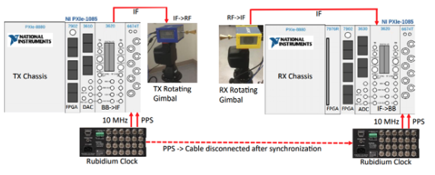

The MPACT Lab at NCSU has an additional pair of mmWave transceiver nodes from NI for channel sounding experiments, composed of one transmitter and one receiver PXI platform operating at 28 GHz and 39 GHz. Two rubidium (Rb) clocks, one master and one slave, provide 10 MHz and PPS signals to the PXI timing and synchronization modules at the transmitter and the receiver. The master Rb clock trains the slave Rb clock so that clock signals are synchronized. The digital to analog converter at the transmitter PXI and the analog to digital converter at the receiver PXI have a sampling rate of 3.072 GS/s. The channel sounder supports 1 GHz and 2 GHz modes of operation. At 2 GHz, where the sounding signal duration is 1.33 µs, the system provides a 0.65 ns delay resolution, corresponding to 20 cm distance resolution of multipath components. The analog to digital converter has 60 dB dynamic range which limits the peak to noise ratio of the power delay profile (PDP) to 60 dB. The sounder can measure path loss up to 185 dB. When measuring the maximum measurable path loss the antenna gains, the gain due to the correlation of the transmitted sounding sequence and the CIR averaging performed at the receiver are taken into account. Rotating gimbals or phased arrays are used to measure the angular profile of the channel at different azimuth and elevation angles. Our lab has two gimbals from Flir and two 4×4 BBox phased arrays from TMYTek. When a rotating gimbal is used, each angular measurement takes ~1 second.
When a phased array is used, measurement time is reduced to ~15 ms. In addition to 28 GHz, we have 39 GHz mmWave heads from NI and 120 GHz THz radio heads from VDI which will allow us to perform channel measurements at additional bands. A sample beyond-wall mapping experiment at 28 GHz is illustrated on the left.
A new advanced and unique RF capability that enables RF testing from 1-25 GHz, 34 GHz to 50 GHz, and 75 GHz to 110 GHz is also available at the OU Advanced Radar Research Center. The 9-axis mm-wave system is equipped with a Copper Mountain C4209 Vector Network Analyzer (VNA) that provides industry-leading dynamic range and sweep speed, with all the features engineers have come to expect included in our software. This VNA is frequency-extender compatible and is the anchor network analyzer for the CobaltFx frequency extender system, which provides a frequency operation from 75 GHz to 110 GHz.
To further expand testing and design capabilities at mmWaves, the RF COM Lab at FIU is equipped with a u-lab Chamber from Microwave Vision Group (MVG), which can be used for compatibility and interoperability testing between 18 and 110 GHz. It features an anechoic chamber, a precision positioning system, RF equipment (network analyzers, waveguides, probes) and compute resources for post-processing.
This project will also take advantage of the significant experimental and testing infrastructure and experience available at UCSB under the SRC ComSenTer program. This center draws on novel systems architectures and signal processing algorithms, sophisticated high-frequency IC designs, and advanced semiconductor technologies. Key to these networks is massive spatial multiplexing, i.e. the use of tens or hundreds of simultaneous, independently-aimed signal beams, each carrying an independent data stream. Such multiplexing is enabled by short signal wavelengths and by transmitters and receivers having arrays of tens to hundreds of signal channels. UCSB has significant resources for the characterization of D-band integrated circuits through ComSenTer, which has also focused on massive MIMO development for the SRC industry consortium. To test 16-element arrays, UCSB has a pair of Xilinx ZCU-111 RFSoCs. Additionally, UCSB has a full range of network analyzer extenders for measurements between 75 GHz and 300 GHz as well as power meters. Additionally, UCSB maintains three millimeter-wave probe stations for characterization of ICs.
The Wireless Networking Laboratory at UT Austin is equipped with ACER TravelMate laptops with 60 GHz cards, and Airfide, TP Link WiGig access points for 60 GHz experiments.
Extremely Mobile Spectrum Facilities
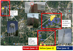
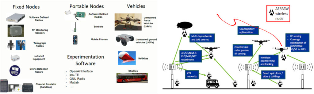
AERPAW. NC State has received an NSF award (CNS-1939334) to develop Aerial Experimentation and Research Platform for Advanced Wireless (AERPAW), a 5 year project which started Sep. 1st, 2019. From Year 2 onward, AERPAW is expected to deploy several mmWave equipment items that will be available for experimentation by the broader research community. These items will rely on software defined radios and support phased array platforms at 28 GHz and 39 GHz. A tentative deployment map for AERPAW nodes can be seen in on the right (top figure), together with pictures of the different deployment locations, which highlight the heterogeneity of this testbed.
To further highlight the heterogeneity and the mobile nature of the testbed, The figure on the right (bottom) lists the equipment that is and/or will be available to AERPAW and possible experiment scenarios. Further information about AERPAW, including equipment, deployment areas, and sample experiments, can be found at https://aerpaw.org/.
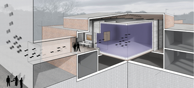
Northeastern Expeditionary Cyber and Unmanned Aerial Systems Lab (ECUAS). The ECUAS Research and Development Facility provides a suite of capabilities for Science, Engineering, Technology Development, Test and Evaluation on advanced systems across all technology readiness levels. With a broad range of capabilities, the ECUAS Facility is a platform through which to enable discovery and innovation in cyber systems, electromagnetic systems, position, navigation and timing systems, autonomous systems, and flight systems. It consists of both indoor and outdoor test ranges for testing aerial and ground systems, antennas, cyber, radio, network, navigation and communications equipment. The lab is one-of-a-kind with the ultimate goal of being flexible and configurable to support current and future R&D activities and innovation across a broad range of interdisciplinary challenges at the tactical edge in order to advance the state of the art and solve real world problems.
Indoor Wireless Test Range Capabilities:
- Indoor 50’x50’x22’ Faraday Cage/Anechoic Chamber for operation of unmanned and autonomous systems as well as testing of wireless devices in 100% controlled RF environment
- State of the art software defined radios and 64 antenna array to transmit/receive arbitrary waveforms for jamming, interference, spoofing, communications and control (more detail on this below)
- One-of-a-kind data-driven forensics and analytics center
- Navigation testing (w/ jamming, spoofing, interference) using Global Navigation Satellite System (GNSS) Simulator
- Cyber security testing of wireless devices for vulnerability/exploitation analysis
- Multi-axis antenna positioner w/ +/-0.5o accuracy for antenna testing/analysis
- EMP test capability (RS105) for radiated susceptibility of small devices/systems
- Characterization of emissions of wireless devices to enable things such as UAS/UGS Detection/Tracking
- Networking for autonomy, swarms and massive MIMO
- Able to test large drones up to 1300+ lbs with integrated tether points
- RF testing from 300MHz to 18+GHz
- 24 Camera 360o HD camera optical tracking system for precise indoor positioning in 50,000 cu. ft. volume
- State of the art RF and electronics measurement equipment
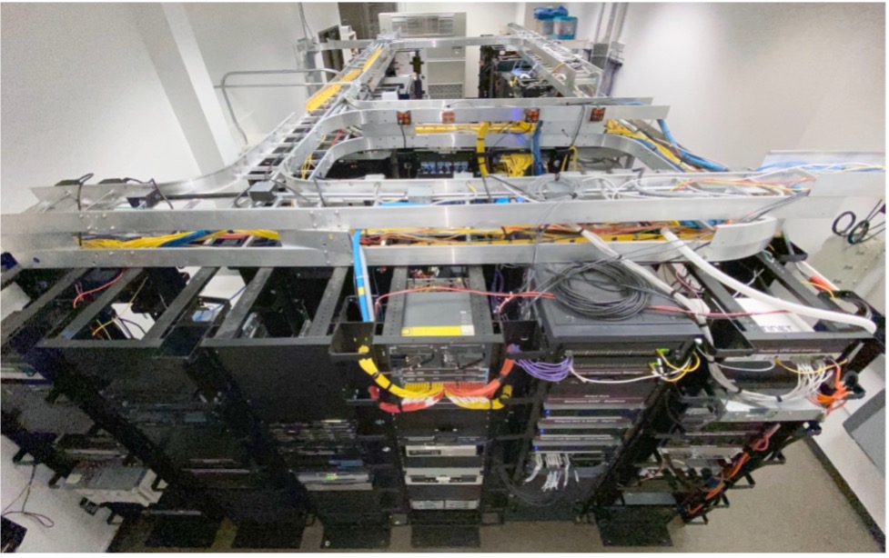
The indoor (RF anechoic chamber) area of the facility can be used as an SDR testing facility. It is composed of a 4×4 grid of USRPs X310 radios connected to the ceiling, each with a double-CBX daughterboard with 4 antennas. The grid covers a 60×60×30 ft. tridimensional indoor space (shown in the figure on the right, top). CBX daughterboards have an operational frequency range of 1200-6000 MHz, allowing the radio to operate in both licensed and unlicensed spectrum portions (GSM, LTE, ISM, TVWS, among others). Each is equipped with a pair of Ettus VERT2450 antennas, transmitter and receiver, respectively. All the 16 USRP X310 are placed in a single rack, in a dedicated utility room, while the fixed grid positions are occupied by 16 antenna pairs. Each USRP drives four antennas, fixed to the ceiling grid. 120 ft. long low path-loss cables (LMR600) connect each USRP radio with its antennas. All the USRP radio devices are frequency- and sample-time synchronized. A cascade design of three Ettus OctoClock-G CDA-2990 clock distributors is employed to provide 10 MHz and 1 PPS signals reference to each radio device with an accuracy better than 25 ppb. The same utility room hosts sixteen DELL Precisions Workstations T5810, organized in a similar rack.
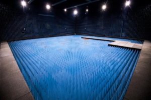
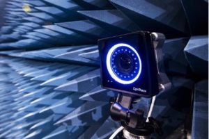
The facility is equipped with a state-of-the-art Optitrack system that tracks the movement of any mobile node indoor in cm-level accuracy in three dimensions with cameras. This will enable repeatable experiments with controlled mobility.
The indoor facility also internally opens up to the outdoor facility for studying complex scenarios. The outdoor setting (see figures below) houses movable programmable radios, SDRs, real-time kinematic (RTK) GPS systems, jammers, and weather tracking options. The surface will also be purposed to study various terrain challenges with ground vehicles.
Outdoor UAS Test Range Capabilities:
- Outdoor 150’x200’x60’ netted enclosure for unobstructed GPS enabled flight testing. Flight in netted enclosure eliminates need for FAA approval.
- Large enough to support multiple simultaneous test events
- Outfitted with various UAS obstacles for setting up a wide range of flight tests
- Paved surface for testing air and ground systems, including UAS/UGS teaming exercises
- Equipped with enhanced kinematic GPS for extremely precise centimeter positioning
- Steady state/gust wind test capability for small drones (<150g) for performance characterization under varying wind conditions
- Interconnected flight path between outdoor and indoor test ranges for seamless transition of drones between the two
- 60’ observation deck in adjacent building for flight test viewing

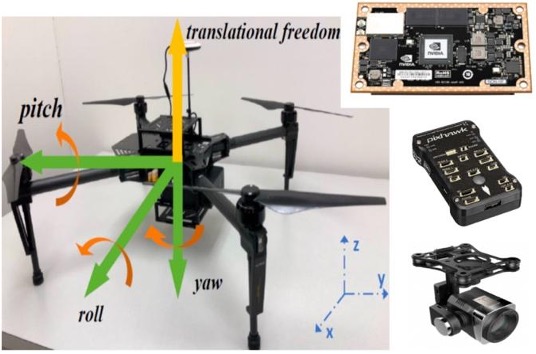
The drone platform (left figure) is based on the Solo developed by 3DRobotics, which offers a highly programmable interface using the widely adopted Pixhawk family controller. The possibility to tune flight parameters of the drones in real time makes it a suitable platform to establish dynamic communication links using SDR. Each drone carries a SDR on its Accessory Bay along with a native Linux operated Intel Processor working as Companion Computer to control and synchronize the information exchange between the drone OS and the SDR. The lightweight USRP B200-mini radios are adopted as the SDR, which is controlled by the Intel processor via USB 3.0 using GNU Radio to establish an adaptable and secure ground-to-air and air-to-air communication links. The drones are controlled using Pixhawk-compatible control messages
To this end, the control messages are first encapsulated in Mavlink packets, which are then converted to Python objects using PyMavlink, converted to B200mini-compatible MAC- and PHY-frames using GNU Radio, sent to the drone-carried SDR over radio links, and finally fed into the Pixhawk family controller embedded in the drone.
ECUAS also provides machine shop, electronics shop, and 3D printing facilities, as well as space to accommodate needs of students, faculty, visitors, and industry partners.
RF Design, Fabrication, and Testing Facilities
Jet Propulsion LaboratoryFacilities. JPL has world-class submillimeter-wave device fabrication capability and submillimeter wave test and measurement facilities. Considerable cost savings are achieved by leveraging unique submillimeter-wave technology developed for a number of NASA missions and R&D projects (HIFI/Herschel, MIRO/Rosetta, MLS/Eos Aura, SBIR, PICASSO, MatISSE, APRA, and SAT). The group has five fully equipped flight qualified submillimeter wave test laboratories including complete micro-assembly and a micro-precision metal fabrication capability.
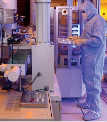
Fabrication/Device Release: Fabrication occurs in a 100,000 square foot state-of-the-art microdevice fabrication facility (MDL) with deep trench and GaAs RIE, MBE, MOCVD, nanometer scale e-beam lithography, stepper aligning, wafer bonding, and all other necessary clean room equipment. The figure on the right shows JPL researcher Dr. Choonsup Lee handling GaAs wafers during one of our Schottky diode based frequency multiplier fabrication processes. Our group already employed this facility to fabricate state-of-the-art transmitters up to 2.7 THz.
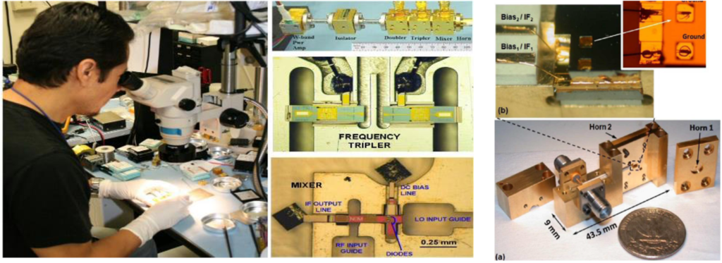
Assembly: The SWAT assembly labs include a suite of micro-assembly hardware including stereoscopes, bonders, pull testers, etching, plating, probe stations, lithography etc. and the usual array of electronic device test equipment. Shown in the figure below is one of several assembly stations as well as photos of blocks (inside and outside) assembled in our laboratory.
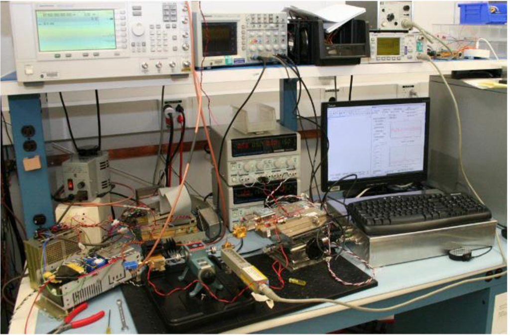
Testing: RF test capability includes tunable frequency multiplied LO sources from 50-2700 GHz, and complete mixer and multiplier characterization from 100-4800 GHz. For testing the receivers, our team has room temperature and cryogenic detectors and passive components covering all commercial waveguide bands up to 330 GHz, custom mixers and sources at scattered frequencies from 100-2700 GHz, as well as absolute power, frequency and spectral content measurement equipment throughout the submillimeter range. We possess six PM4 Erickson calorimeters with all the necessary transitions to fully characterize sources up to 4. 7 THz. We also own special power sensors for cryogenic/vacuum testing. Additional terahertz measurements can be done using Thomas-Keating power meters. A sophisticated custom sensitivity (noise temperature) test set has been assembled that simultaneously determines noise temperature, gain, and IF output matching for full receiver characterization from 1-20 GHz IF.
RF Testing Facilities at TAMU. TAMU PIs also have access to a state-of-the-art automated antenna measurement system. It includes a newly constructed anechoic chamber from ETS Lindgren. The chamber interior measures 24 ft, 10 ft, and 6.5 ft in length, width, and height, respectively. It has been designed to provide high fidelity measurements from 800 MHz to 140 GHz. This features a quiet zone with better than 20 dB attenuation using an automated measurement system for RF, microwave, and millimeter-wave frequencies based on components from Keysight Technologies and Virginia Diodes, Inc. This structure is instrumental to prototyping and testing.
Circuit Design, Tapeout, and Testing Facilities at Northeastern. For circuit design and layout, Northeastern University has the license and the installation of complete Cadence and Synopsys design suites, including post-layout synthesis and formal verification tools. For technologies for circuit tapeouts.
Fabrication Facilities at OU. The OU Radar Innovation Library is equipped with fabrication machines for RF circuits and antennas, which include:
- LPKF Protomat Machine
- LPKF Protolaser Machine
- Electroless- and electro-plating setup
- Multilayer lamination capabilities
- Extensive soldering and rework equipment
- Polymer chemical vapor deposition
- 3D solid fabrication: Form 3
Fabrication Facilities at FIU. FIU is equipped with:
- Fujifilm DMP-2831 for film printing/prototyping
- LPKF ProtoMat S103 circuit board plotter
- Makerbot 3D printer Z18
Fabrication Facilities at GA Tech. Dr. Hua Wang’s lab at Georgia Tech is equipped with a comprehensive set of RF fabrication facilities:
- CMOS MPW Tapeout Runs and Wafer-Level Post Processing (Provided by Globalfoundries). Dr. Wang has established a long-term collaboration relationship with Globalfoundries since 2012. Globalfoundries will provide multiple CMOS Multi-Project-Wafer MPW runs per year to facilitate the CMOS IC prototyping. Therefore, the PI has secured CMOS tapeout runs at NO COST to NSF.
- Packaging Facilities (Georgia Tech IEN facilities). Dr. Wang’s lab has access to all the world-class fabrication, packaging, and micromachining facilities at Georgia Tech Institute for Electronics and Nanotechnology (IEN), which is primarily located at the Pettit Microelectronics Research Center and the Marcus Nanotechnology Building. The Pettit center houses an 8,500-square-foot cleanroom (75% class 100, 25% class 10). The Marcus building includes an additional 10,000 square feet of semiconductor cleanroom space for nanoelectronic device (top-down) fabrication as well as 5,000 square feet of biological (bottom-up) cleanroom space. The facilities related to the proposed project are listed as follows.
- Westbond wirebonder (Au and Al) for both wedge bonder and ball bump bonder
- TPT bonder and flip-chip bonder for flip-chip packaging up-to 180GHz
- Automatic dicing saw
- A wide variety of microscopes, profile meters, SEM, and AFM
- Other fabrication facilities, including laser micromachining system, sputters, epitaxy machines, mask aligners, plasma thermal deep RIE, plasma thermal CVD, Hitachi 3500H SEM, Semitool spin rinse drier, dark room for mask generation
Other. Fabrication and state-of-the-art electronics facilities are also provided by UC Berkeley’s Space Science Laboratory.
Other Technical Facilities
Disaster City at TAMU. Disaster City is an outdoor public safety training and exercise that is housed on several hundred acres of derailed trains, underground tunnels, collapsing buildings, scalable structures and training and testing facilities. The facility is managed by the Texas Engineering and Extension Service (TEEX) which is a part of the Texas A&M University System. TEEX trained 204 first responders in 2019 at Disaster City, RELLIS and other sites around the world and is likely the largest first responder training organization in the world. The TAMU ITEC AWARE testbed has a dark fiber circuit to Disaster City to connect RAN to the cores. This connection is used several times a year for various tests and exercises.
RF Testing Facilities at TAMU. TAMU PIs also have access to a state-of-the-art automated antenna measurement system. It includes a newly constructed anechoic chamber from ETS Lindgren. The chamber interior measures 24 ft, 10 ft, and 6.5 ft in length, width, and height, respectively. It has been designed to provide high fidelity measurements from 800 MHz to 140 GHz. This features a quiet zone with better than 20 dB attenuation using an automated measurement system for RF, microwave, and millimeter-wave frequencies based on components from Keysight Technologies and Virginia Diodes, Inc. This structure is instrumental to prototyping and testing.
Cyber-Physical Systems Lab at TAMU. The lab features a complete environment of sensing, ad hoc wireless network, and closed loop control. It consists of two video cameras and ten infrared cameras covering multiple cars on a platform. Laptops controlling the cars are networked by a wireless network. Subsystems include image processing, planning and scheduling, distributed time synchronization, wireless and wired networking, and receding horizon control. The goal of the lab is to study the architectures and abstractions appropriate for sensing and actuation over networks, to study issues relevant to the convergence of control with communication and computing, to develop and test algorithms and solutions, and to develop middleware to facilitate such convergence. The lab also has a cascaded two-tank water system used to test security of cyber-physical systems.
Texas Tech University Testing Range. Texas Tech University has a mostly undeveloped 400 acre satellite campus in Junction in the Texas Hill Country, for field tests of prototyped equipment in rural settings.
Computing Resources
Northeastern University. The team at Northeastern University has access to a total of 4 NVIDIA DGX servers, purpose-built by NVIDIA for deep learning. Two NVIDIA® DGX Stations are equipped with four NVIDIA® Tesla® V100 Tensor Core GPUs (a total of 20,480 NVIDIA CUDA cores; 2,560 Tensor cores), integrated with a fully-connected four-way NVLink™ architecture, delivering 500 teraFLOPS. Each station also has one 20-core Intel Xeon E5-2698v4 CPU, 256GB DDR4 2133MHz System Memory, and four 1.92TB SSDs (one for OS and three in RAID0 for high-speed cache).
Other back-end processing is provided by eight DELL Servers (quad core multi-processor machines with 24, 48, 64, 128 and 196GB RAM, with over a TB of fast hard drive each) for simulations and mathematical software. The Northeastern team has specialized active licenses for: ANSYS H FSSv12 software for RF modeling, latest MATLAB/SIMULINK releases and all necessary toolboxes, academic evaluation license for OPNET and other open-source network simulator installations, such as ns-2, ns-3, Castalia and GreenCastalia. Additional current computing resources include a host grid of 19 computers, 16 of which each have 48 CUDA cores while the other three each have 1280 cores with 6 GB GDDR5 GPU.
The PI team will also leverage the computational and storage capabilities of a powerful computational cluster, called the Discovery Cluster, housed in the Massachusetts Green High Performance Computing Center (MGHPCC). MGHPCC is a joint venture between Northeastern, Boston University, MIT, Harvard and the University of Massachusetts system. The 90K square foot, 15 megawatt facility was completed in November 2012 and is located on an 8.6 acre former industrial site in Holyoke, MA. The machine room floor at MGHPCC has built-out capacity that can house roughly 10K high-end computers with hundreds of thousands of processor cores, and expansion capabilities in the building for a further 10K computers. MGHPCC houses and supports NEU’s Discovery cluster, and also provides connectivity to Internet2.
The Discovery cluster provides access to over 20,000 CPU cores and over 200 GPUs for all faculty and students free of charge. The currently available hardware for research consists of a combination of 2.4 GHz Intel E5-2680 v4 CPUs, the latest 2.1 GHz Intel Xeon Platinum 8176 CPUs, and a selection of NVIDIA K80, P100, V100, and T4 GPUs. More specifically, the cluster has 48 GPU nodes, with each of the 32 nodes (compute-2-128 to compute-2-159) having an NVIDIA Tesla K20m GPU with 2496 computing CUDA cores. These GPU servers can be accessible via 10Gb/s TCP/IP backplane. There are 16 more compute nodes with a NVIDIA Tesla K40m GPU each (compute-2-160-compute-2-175). In addition, there are 8 compute nodes each with 8 NVIDIA Tesla K80m GPUs and 0.5TB of RAM. Additional NVIDIA A100 GPUs are currently being installed in the Discovery Cluster through the AI Jumpstart program, with a total of 4 NVIDIA DGX A100 (and 32 NVIDIA A100 GPUs).
Discovery is connected to the university network over 10 Gbps Ethernet (GbE) for high speed data transfer, and provides 3 PB of available storage on a high-performance GPFS parallel file system. Compute nodes are connected with either 10 GbE or a high performance HDR100 Infiniband interconnect running at 100 Gbps, supporting all types and scales of computational workloads. Full HDR Infiniband connections (200 Gbps) are also available if necessary. A dedicated team of PhD scientists and support staff manage the RC environment and supports researchers in their use of high-performance computing for research and discovery. The computational resources available through Discovery are updated with the newest technologies on a yearly cycle to support the cutting-edge research being performed by Northeastern faculty and students.
Research groups who require access to dedicated computational resources may take part in the Discovery “buy-in” option, integrating their hardware into the Discovery cluster to provide unified access to both private and shared compute nodes for their research group members.
We maintain and manage 16 multi-core servers within the Discovery cluster whose use is exclusively dedicated to the group through the “buy in’’ option, all housed at the MGHPCC: 8 of these servers contain 40 cores (Dual Intel Xeon E5-2680v2 2.8GHz CPUs), of 25M cache and 128 GB RAM, while the remaining 8 servers contain 58 cores (Dual Intel Xeon E5-2680 v4 2.4GHz, 35M Cache), of 35M cache and 512GB of RAM each. We also have one multi-core server within the Discovery cluster, whose use is exclusively dedicated to the group through the “buy in” option and is housed at the MGHPCC (Dell PowerEdge R6515 with an AMD 7402P 2.8 GHz, 24 Cores, 128 MB cache, 256GB RAM, IB 200 HDR). The server is mainly utilized for multi-physics simulations with Matlab and COMSOL Multi-physics.
University of Oklahoma. The OU Supercomputing Center for Education and Research (OSCER) provides the OU community with High Performance Computing (HPC), furnishes hardware and software resources, technology transfer support, and outreach support. OSCER’s primary focus concerns education and research, with all other activities directed toward supporting these goals. OSCER has acquired, deployed and continues to maintain an extensible petascale storage instrument, the Oklahoma PetaStore, which combines capacity for multiple Petabytes (millions of GB) of tape and almost a PB of disk, to enable faculty, staff, postdocs, graduate students and undergraduates at institutions across the State of Oklahoma to build large and growing data collections, at no usage charges (users purchase their own tape cartridges). Researchers also have access to a Linux cluster supercomputer with a peak speed of 111.6 TFLOPs. Additionally, the Linux cluster computer has been set up to run HFSS simulations – dramatically decreasing typical computational electromagnetic simulation time and increasing the complexity of simulations that can be solved.
Florida International University. The FIU team has access to a DELL PowerEdge R740xd work station, with 3.6GHz Intel dual 8C CPUs with 256GB memory, a Linux server with an Nvidia MSI GeForce GTX 1080 Ti 11GB GPU, and a DELL PowerEdge T440 workstation having a 3.6GHz Intel dual 8C CPU with 128GB memory. Additionally, the team has access to CST and HFSS electromagnetic simulation software, MATLAB, NI LabView, the Xilinx FPGA development SDK, and Cadence and Synopsys for integrated circuit design.
Additionally, the Instructional and Research Computing Center (IRCC), part of FIU’s University Technology Services (UTS), houses and manages FIU’s High-Performance Computing resources. They maintain centralized high-performance computing (HPC) resourcesat FIU for the entire university community either for research and education. The IRCC manages the following Panther Cluster Computing environment:
- 2500+ Intel-based cores
- 56 Gbps Infiniband nodes
- 500+ TB high-performance parallel storage
- 40 TB high-performance scratch space
- Processing cores with RAM ranging from 4 GB – 1 TB per core
- 6-node GPU cluster for CUDA jobs
- 3-node visualization environment
- Compute nodes consist of 42 IBM H-Series Blades, 3 Dell PowerEdge C6220 Servers, 32 M420 Dell Bladeswith IB interconnect, one 64 cores IBM x3850 SMP node, 10 M630 (Dual E5- 2698v3, 36 Cores; 1xM1000e, 2xMXL 10GbE Switches, 1xMellanox M4001T Infiniband, with 256 GB RAM, expandable to 768GB) nodes; 6 M830 (Dual E5-2698v3, 72 Cores; 1xM1000e, 2xMXL 10GbE Switches, 1xMellanox M4001T Infiniband, with 1 TB RAM, expandable to 1.5 TB) nodes
- Login nodes, LSF scheduler and management nodes on 4 Dell PowerEdge R420 Servers
- Virtual computing facilities with several operating system images
The environment also supports a suite of over 200 installed software packages that are relevant to a high-performance cluster environment. In addition, FIU provides extensive computing resources to students. The College of Engineering has the Engineering Information Center (EIC) that provides labs with a capacity of 250 students at any given time. A wide range of software is provided on Windows-based and Unix- based machines. EIC also manages all IT aspects ofFIU’s College of Engineering and Computing, including computer maintenance, backups, and redundant remote location backups. Furthermore, RFCOM lab has the following computers and software: (a) three powerful simulation servers, (b) COMSOL Multiphysics with AC/DC, Optimization and RF modules with two research licenses and a 30-user educational license (note that the educational license is a fully capable version of the software), (c) Sonnet, (d) ANSYS multiphysics packages, (e) our own 3-D FDTD custom codes, and (f) EAGLElayout-editor for schematic PCB design. The software by ANSYS/HFSS, COMSOL and Sonnet will be used for RF/electromagnetic simulation analysis and design. Also, a realistic simulation model of the human body with all appropriate material properties is available in our research lab and will be incorporated in simulations.
NC State – The College of Engineering and NC State maintain a state-of-the-art general-purpose academic computing environment known as Eos/Unity, a large-scale distributed system that consists of literally thousands of Unix and Windows-based workstations and servers all over campus. Eos/Unity uses robust, centrally managed storage and application system that features a number of software packages and tools, including simulation and analysis software, and mathematical software. Academic computing environment is operated by a professional support group that provides consultation and basic system and software services.
Virtual Computing Laboratory (VCL) is a cloud computing resource that integrates a large range of computing resources, from blade centers and clusters to idle cycles on individual commodity lab PCs, and delivers them to a large range of computing needs, from individual computing tool usages of minutes to batch jobs of high performance clusters lasting days, through a common scheduling, reservation and access portal. More details can be found on the VCL website http://vcl.ncsu.edu/ .
The following specific computing resources are now integrated with VCL.
- HPC: High-Performance Computing (HPC) operations provides NC State students and faculty with entry- and medium-level high-performance research and education computing facilities and consulting support. This service is complementary and now joint with the NC State Grid operations which build on the NCBiogrid project. The initial configuration consists of a 32 processor (max 166 GFlop) IBM p690 – in production mode, and a 200 processor (peak over 1 GFlop) IBM Blade Center – in production mode. The p690 is supported by 3.5 TBytes of direct attached disk space. The Blade Center is supported by about 2.5 TBytes of blade-distributed on-board disk space, and 14 TBytes of shared network attached disk space.
- GRID: NC State’s Grid project is part of the UNC-OP and NC Grid Computing Initiative. The initial deployment has been in the form of an active NC Biogrid computing node, located at NC State and operational since 2002. It runs both Globus and Avaki grid middleware. This Grid is now being expanded to encompass NC State HPC facilities. Students and faculty have access to Eos/Unity, as well as off-campus and international networks, which provide access to high-performance computers.
The three Research-I Triangle Universities (Duke, UNC-CH, and NC State) have a long and fruitful history of partnership and collaboration in leading edge research. The NC Grid facilities will be complemented with the Scientific Data Management Center facilities (http://sdm.ncsu.edu) which include compute clusters as well as mass storage available over the network. SDM facilities may be used support this project.
North Carolina and NC State University boast one of the most extensive and sophisticated advanced high-performance communications infrastructures available for broad-based use today. The facilities include:
- Research Triangle high-performance production network and testbed (NCNI GigaPoP): a self-healing fiber-optic backbone ring linking Raleigh, Durham, Chapel Hill, and Research Triangle park, operating at OC-48 speeds with drops at NC State, UNC-CH, Duke University, MCNC/NCSC, and several industrial research sites. This facility is currently being upgraded to a 10 Gbps DWDM based implementation.
- Abilene (Internet2): NC State is a member of Internet2 and has Abilene connectivity.
- National Lambda Rail (NLR): NC State is a member of NLR a 10 Gbps national research network.
- NC State’s high-performance production network has capabilities that include 4 and 10 Gbps backbones with redundant 1 Gbps (and in some cases 10 Gbps) drops into buildings and research laboratories that will participate in this project.
- The research network consists of over a dozen high-end ATM, Gigabit, and 10 Gigabit Ethernet switches and edge-devices switches from many vendors. The extent of the research network implementation is comparable to that of the production network and provides similar service coverage. We operate a number of networking protocols within both networks, and we experiment with a variety of them in the research portion of the network. This includes, but is not limited to IPv6, Differentiated Services, and COPS-based policy services.
- NC State has a campus-wide wireless networking solutions (802.11n based) operating in most buildings on campus and in most outdoor heavy-use areas.
The networking facilities described above are available for use in research projects. In addition, facilities in our specialized research and teaching laboratories (Computer Science Undergraduate Networking Laboratory, Centennial Networking Laboratories, and Electrical and Computer Engineering Networking Laboratory, Graduate Networking Laboratory) are being used by courses in hands-on networking, as well as by researchers. Institute for Next Generation IT Systems (ITng) will provide networking technical support, and any additional networking related services, that may be needed for the project (the OSCAR labs facility is administered by ITng). It will also provide advice to the researchers and students. More details about ITng (and OSCAR) are available on the ITng website at http://itng.ncsu.edu.
NC State has a college-wide software license for both REMCOM Wireless InSite and Altair Winprop ray tracing software which will be used in the proposed work. The Wireless InSite can support frequencies up to 100 GHz and provides realistic propagation information for complex topological environments using ray tracing simulations.
Texas Tech University. The TTU team has access to a High Performance Computing Center (HPCC). The HPCC’s primary cluster is RedRaider, with a benchmarked total computing power of 1515 Teraflops, consisting of two CPU partitions and a GPU partition.
University of California – Santa Barbara. For circuit design and layout, UCSB supports software licenses for Cadence Design Systems, Synopsys, AWR Microwave Office, and Keysight ADS. Additionally, packaging requires sophisticated 3-dimensional electromagnetics simulation tools such as EMX (now part of Cadence), Momentum, and Axiem. PI Buckwalter maintains three server clusters to support a variety of design kits and tools.
University of California – Berkeley. Several servers and linux clusters at the UC Berkeley Space Sciences Labs are also available for this work, including over $500,000 worth of donated computing equipment.
University of Texas – Austin. The work will also leverage resources at the Laboratory for Advanced Systems Research (LASR) at The University of Texas at Austin, which consists of over 50 high-end workstations and servers interconnected by 100Mbps Ethernet. The lab will make use of the University of Utah’s Emulab software (http://www.emulab.net) to allow the multiplexing of several large-scale experiments across a collection of 20-30 machines and to vary network performance in a controlled fashion. The Texas Advanced Computing Center (TACC) is a research facility at The University of Texas at Austin and provides advanced computing resources and services to enable computationally intensive research. Furthermore, TACC conducts research and development to enhance the capabilities of these resources. TACC deploys and operates advanced computational infrastructure to enable computational research activities of faculty, staff, and students of UT Austin. TACC also provides consulting, technical documentation, and training to support users of these resources. Through the National Partnership for Advanced Computational Infrastructure (NPACI), these resources and services are also made available to the national academic research community. TACC provides comprehensive advanced computing resources, including:
- High performance computing (HPC) systems of a variety of architectures to enable larger simulations analyses and faster computation times than are possible using computers available to individual researchers, academic departments, and research centers and institutes;
- Advanced scientific visualization (SciVis) resources including computing systems with high performance graphics hardware, large displays, and immersive environments, and high-end post-production facilities to enable large data analysis and promote knowledge discovery; and
- Massive data storage/archival systems to store the vast quantities of data that result from performing simulations on HPC systems and developing visualizations of large data sets.
Most relevant to this proposal, NASCE will have access to a large-scale GPU cluster at the Texas Advanced Computing Center (TACC) – Maverick2. This cluster has just come online (the PIs already have early access) with 96 1080Ti nVidia GPUs; thus, this is ideal for deep RL experiments. We also have access to the Stampede2 supercomputer consisting of 4,200 Intel Knights Landing nodes (each with 68 cores and 100+ GB of RAM), and more than 1500 Intel Xeon nodes.
Texas A&M University. The team has access to super-computing facilities through the TAMU high performance research computing group, whose mission is to enable research and discoveries that advance sciences and technologies. This group operates advanced computing and data resources to enable computational and data-enabled research activities of students, faculty, and researchers. This facility maintains high-performance computing clusters. (1) Terra is a 313-node heterogeneous Intel cluster from Lenovo with an Omni-Path Architecture interconnect and 48 NVIDIA K80 dual-GPU accelerators. There are 304 nodes based on the Intel Broadwell processor and 16 nodes based on the Intel Knights Landing processor. (2) Ada is a 775-node hybrid cluster from IBM/Lenovo with Intel Ivy Bridge processors and a Mellanox FDR-10 Infiniband interconnect. Ada includes 68 NVIDIA K20 GPUs supporting applications already ported to GPUs, and 24 Intel Xeon Phi 5110P co-processors supporting applications benefiting from Knights Corner Phi cards. In addition, the PIs have access to Lonestar 5, which is a multi-university cluster hosted at the Texas advanced computing center.
The TAMU PIs are also equipped with 12 workstations, all of which are high performance machines with top-of-the-line NVidia graphics cards for GPU-based computations. These are used for fast simulations to identify candidate algorithms, which are then simulated extensively using the high-performance clusters described above. Several are connected to software defined radios to enable ML-assisted network experiments. Also available are assorted laptops that drive the communications equipment.
Georgia Tech University. The team has access to software suites for the designs of integrated circuits/systems and packaging:
- Full Cadence suite including Spectre, SpectreRF, Ultrasim, and Virtuoso
- Mentor Graphics suite including Calibre
- Full Agilent suite including Advanced Design System (ADS), SystemVue, and Ptolemy
- EM simulation software: Ansoft HFSS, EMX, and Sonnet
- Multi-physics simulation software: COMSOL
- Other software suites: Matlab, Mathematica, and LabView.
Collaborative/Managerial facilities and equipment
NASCE will be headquartered on the fourth floor of Northeastern’s Interdisciplinary Science and Engineering Complex, co-located in the office spaces of the Institute for the Wireless Internet of Things, also directed by PI Melodia. The headquarters occupies ~2000 square feet of meeting space and faculty office space in contiguous or near-contiguous offices, within a larger collaborative environment for researchers, staff and students. This dedicated space will allow for the PI, EC at NU and staff to effectively manage the program and conduct day-to-day activities such as facilitation of meetings, webinars, events, student programs, required reporting functions and development and maintenance of web presence. The dedicated conference room and a shared conference room can each hold up to 20 people, with access to a larger seminar room on the first floor that can hold up to 300 people. Additional offices can easily be added to this configuration in accordance with team needs. All meeting spaces (conference rooms, seminar venue) are fully equipped with projectors and connectivity for audio and webinar participation.

In addition to the dedicated headquarters space, all NASCE researchers have dedicated office space and associated equipment provided by their institutions including computers, printers, scanners, phones, projectors and desk space for researchers and students.
Institutional support resources
The resources listed below will be leveraged by the NASCE leadership both directly as described in the project description, and as consultative partners as needed.
- Northeastern’s Center for STEM Education was established in 2001 and seeks to build and support a community of educators, researchers, and students, with the collective goal of strengthening the K-20 STEM educational ecosystem. The Center is housed in the College of Engineering and works with University leadership to support community engagement and diversity efforts. In addition, the Center staff supports individual faculty members’ Broader Impact and collaborative research efforts. The Center provides professional development for students and student organizations interested in supporting STEM educational outreach efforts. The Center is currently led by an Administrative team with the direct support and guidance of partner faculty. The Center provides yearlong programming to engage and support K-14 students and teachers supported by a large cohort of student volunteers – currently, 75 volunteers who on average spent 11.6 hours of service per semester.
- Northeastern’s ADVANCE Office of Faculty Development provide programs and trainings to further develop and support a thriving faculty, including resources for postdoctoral associates.
- The Northeastern PhD Network is an organization designed to build community among PhD students. The Network provides students with support and resources university wide to enhance their educational experience and career preparation.
- Northeastern’s Office of General Counsel, Center for Research Innovation, and Research Enterprise Services are available to support the NASCE team on any specific research administration, business and/or legal questions that may arise
- Northeastern’s Office of Institutional Diversity and Inclusion promotes a commitment to equal opportunity, affirmative action, diversity, and social justice while building a climate of inclusion on and beyond campus. The office advises and assists the president, senior administrators, and the campus community with implementing leadership strategies that advance diversity and contribute to the university’s aspirations.
NASCE partner institutions all have common institutional resources particularly in support of students from underrepresented groups. For example, there are numerous dedicated staff who can be leveraged such as the NCSU Minority Engineering Programs (https://www.engr.ncsu.edu/wmep/mep/) and Women in Engineering Programs (https://www.engr.ncsu.edu/wmep/women-in-engineering/). Similar programs exist across NASCE campuses, including NU, OU, UCSB and beyond. Additionally, student chapters for students who are URGs, e.g. SWE, AISES, SHPE and NSBE, will be leveraged as appropriate beyond the formal relationship with the 50K coalition that is described in the project description to, for example, recruit students to participate in REU programs or for graduate studies.